Patch panel designer
Patch panel designer for AV and broadcast panels
Lay out a custom patch panel socket by socket, label the front and the back, check it in 3D, then export the faceplate as DXF and a build sheet for whoever wires it. The finished panel drops into your signal flow diagram with every socket as a port.
Written by Callum Buckley ·
30-day free trial. No credit card needed.
What can I design: rack panels, wall plates, patchbays?
Three kinds of panel: rack panels for 19" racks, wall plates, and stage boxes. Rack presets cover the common D-series layouts from 1U 6-way to 4U 64-way. Plate presets cover UK 1, 2 and 3-gang, US 1 and 2-gang, and two stage box sizes.
Presets are a starting point. Panels go up to 8U and 8 rows, rows can hold different numbers of sockets, and you can split a panel into named sections such as CAMERAS or COMMS.
Which connectors and D-series cut-outs are supported?
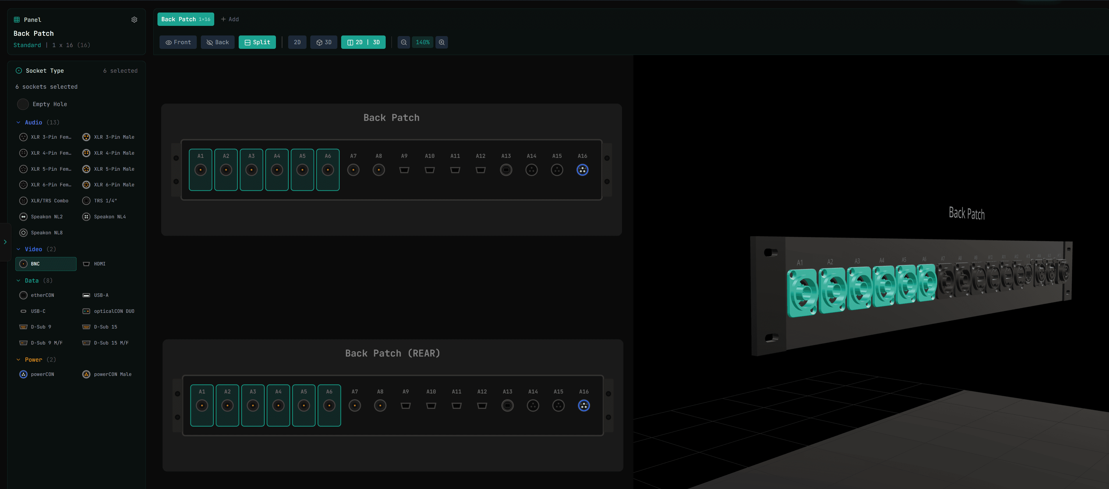
Each hole takes a connector from the socket list, and the hole size defaults to the 24 mm D-series cut-out. The list covers the connectors AV and broadcast panels are usually built from:
| Group | Connectors |
|---|---|
| Audio | XLR 3, 4, 5 and 6-pin (male and female), XLR/TRS combo, 1/4" TRS, speakON NL2, NL4 and NL8 |
| Video | BNC, HDMI |
| Data | etherCON, USB-A, USB-C, opticalCON DUO, D-Sub 9 and 15 |
| Power | powerCON (male and female) |
Feed-throughs get the right gender on each face: an XLR feed-through that is female on the front is male on the back, while a BNC or RJ45 coupler is the same on both sides.
A worked example: a rear panel for a camera rack
- Start from the 1U 16-way D preset. The holes are spread evenly across the 19" opening.
- Select sockets 1 to 6 together and set them to BNC for the camera SDI feeds. Add HDMI, etherCON and XLR to the next holes, and powerCON at the end.
- Give each socket a front label, such as CAM 1 SDI, and note how the back is terminated and which cable lands on it.
- Switch to the split view to see front, rear and 3D side by side and check nothing reads backwards from the rear.
- Export the DXF for the metalwork shop and the PDF build sheet for the person wiring it.
How do I label every socket front and back?
Every socket has its own label, signal, front connector, rear termination, rear cable and notes, and you can edit several sockets at once. Labels show on the 2D drawing, the 3D view and every export, so the engraving file and the wiring sheet always agree.
Can I use a pre-punched panel I can buy?
Yes. Choose a punched panel from the CPC catalogue and Patchify builds it with the right number of holes. For 13 models, from the Penn Elcom R2269 and R1269 ranges and Adam Hall 872215, the hole positions come from the maker's drawing.
Where no drawing is available, the holes are spread evenly and the designer says so, so you can check the datasheet before anyone drills or orders.
What do the exports include?
| Export | What it is for |
|---|---|
| DXF faceplate | Real millimetre dimensions on separate layers for faceplate, holes, labels and dimensions. Opens in AutoCAD, BricsCAD and Revit. |
| PDF build sheet | The faceplate plus a wiring schedule with a tick column for whoever terminates it. |
| Excel wiring schedule | One row per socket: label, signal, front connector and gender, rear termination, cable and notes. |
| Parts list | A CSV of connector quantities to order. |
| PNG image | For quotes, emails and documentation. |
How does the panel connect to the cable schedule?
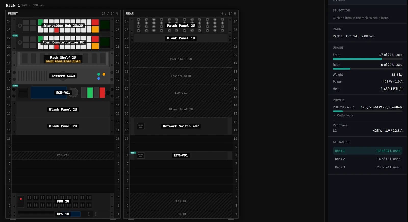
Place the finished panel on your signal flow diagram and each socket becomes a port you can cable to. The project report then prints a panel label sheet listing each socket, its label, connector, cable number and what it connects to.
For quick one-off cable labels without an account, use the free cable label generator.
Which plan includes the patch panel designer?
The patch panel designer is in every paid plan, from Starter at $15/month, and in the 30-day trial. See pricing for the full list.
Questions
Can I design a wall plate or floor box panel?
Yes. Choose a wall plate when you create the panel. Presets cover UK and US gang sizes, and you can set your own width and height.
Does it make engraving or laser-cutting files?
The DXF export has the faceplate outline, holes and labels on separate layers at real size, which is what most engraving and cutting shops ask for. Check their requirements before sending.
Can I see the back of the panel?
Yes. Front, rear and split views show both faces, and the 3D view shows the panel with its connectors.
Is there a size limit?
Panels go up to 8 rack units and 8 rows of sockets.
Try it on your next job
Draw the system once and get the cable schedule, rack and PDF pack from the same project.